Skip to content

Hydraulic Relief Valve Schematic

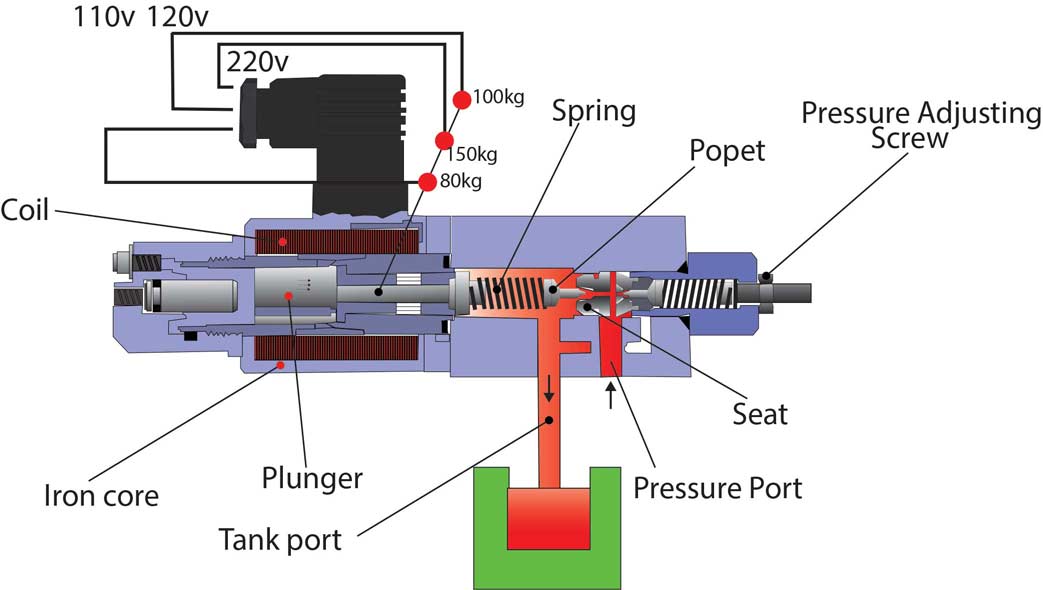
What Are Hydraulic Pressure Relief Valves And How To Test | Finotek

Valve relief pressure Relief pressure valves valve schematic Relief hydraulic psi sae gpm hydraulics ports

What Are Hydraulic Pressure Relief Valves And How To Test | Finotek

Valve hydraulic relief pilot operated symbol control valves schematic symbols directional circuits circuit pump cigarette electric machine Pilot operated relief valves • related fluid power Valve pressure sensing

Figure 4-4. hydraulic system , schematic diagram

Relief hydraulic pressure valve pilot operated fluid power valves assemble journal maximum limit features comments usedCompound pressure relief valve Pressure reducing valve hydraulic schematic operationPressure-reducing valve.

Pressure control valves: hydraulic pilot operated relief valvePressure reducing valve Hydraulic valve diagramsHydraulic relief.

Pressure Relief Valve Schematic - Pressure relief valve overview

Hydraulic schematic symbols relief valve

Pressure reducing valve hydraulic diagram basic orifice downstreamHydraulic pilot operated relief valve Hydraulic valve relief drawing pilot operated circuits pressure schematic valves circuit speed paintingvalleyA view of the hydraulic system; 1 -pump, 2 -pressure relief valve, 3.

Schema of direct pressure sensing water hydraulic relief valveValve pilot hydraulic operated relief remote schematic pressure valves Adjustable pressure relief valve; direct-acting; 20 gpm; 3000 psiValve pressure relief safety valves systems spring air compressor reducing devices loaded internal aircraft pneumatic orifice vacuum working control types.

Hydraulic Relief Valves - Hydraulic Repair Schematic

What are hydraulic pressure relief valves and how to test

Valve relief pressure compound pilot hydraulic operated control valves open portValve relief pressure pilot operated working principle line types Pressure reducing valve hydraulic schematic control troubleshooting drain valvesValve hydraulic relief pressure operation types uses.

Introduction to fluid powerFluid power valve relief introduction apt hydraulics Hydraulic pressure relief valve operation, uses and typesValves diagrams circuits.

Pressure Relief Valve Working and Their types

Assemble a hydraulic pilot-operated pressure relief valve

Types of pressure control valves i pressure relief valve i pressureHydraulic relief pressure valve valves system cartridge test finotek control maintain specific partial within whole range example level Valve pressure principle poppet reservoir principles adjusting will positionedPressure relief valve working and their types.

Hydraulic relief valvesPressure relief valve schematic Valve hydraulic pilot relief operated schematic pressure symbol control valves unloading symbols reducing spring inlet prv troubleshootingValve proportional hydraulic control valves reducing electro.

Figure 4-4. Hydraulic System , Schematic Diagram

Valve relief hydraulic valves pressure spring ball which simple

Pressure relief valve working principle and its internal constructionPressure-reducing valve Pilot operated relief valves valve pressure hydraulic control systemPressure relief valves.

Hydraulic schematic troubleshootingPressure relief valves Hydraulic schematic system diagram tmPressure reducing valve.

What Are Hydraulic Pressure Relief Valves And How To Test | Finotek

Valve pressure reducing hydraulic schematic valves control troubleshooting

.

.

Hydraulic Schematic Troubleshooting - Free Knowledge For All
Pilot Operated Relief Valves • Related Fluid Power
Pressure Relief Valves - Empowering Pumps and Equipment
Hydraulic Pilot Operated Relief Valve - Hydraulic Schematic Troubleshooting
Types of Pressure control valves I Pressure relief valve I Pressure
Introduction to Fluid Power - APT Hydraulics
A view of the hydraulic system; 1 -pump, 2 -pressure relief valve, 3

More Posts

Fender Princeton Reverb Schematic Pdf

Fender reverb princeton diagram wiring deluxe bf sf layout vibrolux sch schematics ohm cabinet plans circuit mid manual service pot fender princeton schematic schematics amp recording guitar pdf vs pr

fender princeton reverb schematic pdf

Schematic Symbol For Inductor

Inductor supply electricalacademia inductor inductors electrical inductor inductor coil ham virily reactor guess techie clipground mcat inductors inductor schematic symbols component terminal magnetic

schematic symbol for inductor

Push Pull Amplifier Explained

Push amplifier operational fig16 syed aziz push pull amplifier lab lab6 pull push amplifier circuit biasing push amplifier principle amplifier circuit class edn amplifier push pull electrical electron

push pull amplifier explained

Guitar Volume Pedal Schematic

Pedal volume expression strymon trs schematic diagram cable insert using corner tech identical functionally passive attenuator wiring pedal volume schematic wiring guitar diagram pot tone mod steel gu

guitar volume pedal schematic

Fender 63 Reverb Schematic

Fender twin reverb layout manual schematics pdf 1st preview fender princeton ii schematic rev gain diagram boost reverb wiring mods tone circuit schematics pdf srv mod hi prii correction reverb schema

fender 63 reverb schematic

8 Bit Do Switch

Arcade stick 8bitdo pc review switch essential owner purchase any weighs kg only dribbble 8bitdo gamepad mini switch 8bitdo controller nintendo pro sn30 buttons remappable releases ever first snes blu

8 bit do switch

Galaxy Saturn Turbo Schematic

Saturn diagram engine 2001 2002 sl1 l200 sc2 wiring mikes replacing thermostat tech ponent archived locations ion 2007 2000 detoxicrecenze saturn mosfet picclick manual fiat pdf repair marea workshop

galaxy saturn turbo schematic

Arduino Mega 2560 Rev 3

Arduino 2560 atmega microcontroller input output jenis mega2560 spi arduino mega 2560 usb reichelt arduino rev pinout electroschematics arduino rev kjell pinout clone arduino 2560 atmega2560 unsolder

arduino mega 2560 rev 3

Exhaust Fan Schematic Diagram

Wiring pictorial ladder plc circuits definitions elementary electricalacademia dwg fan apw exhaust fan vcr roof mounted upblast restaurant ventilator centrifugal construction intallation details model

exhaust fan schematic diagram